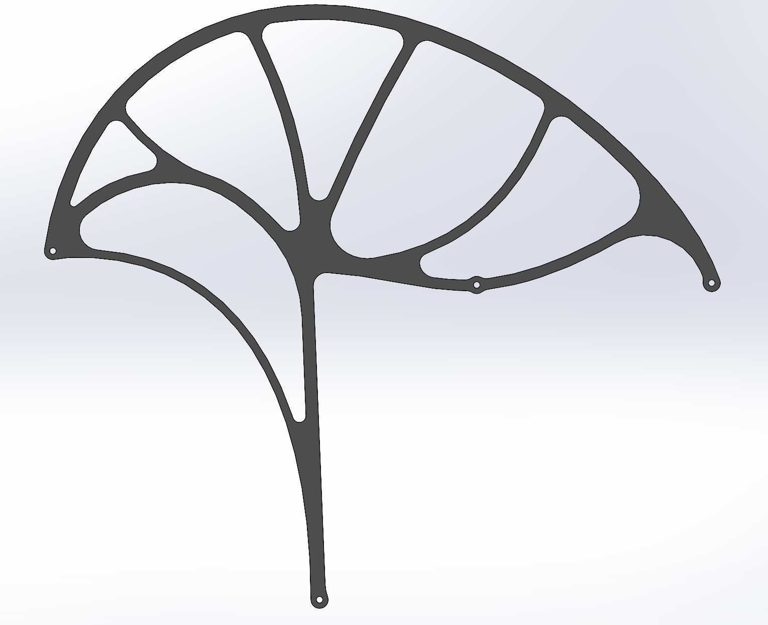
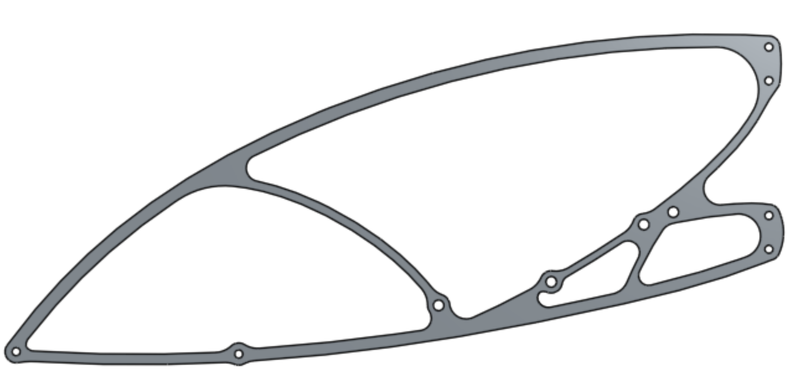
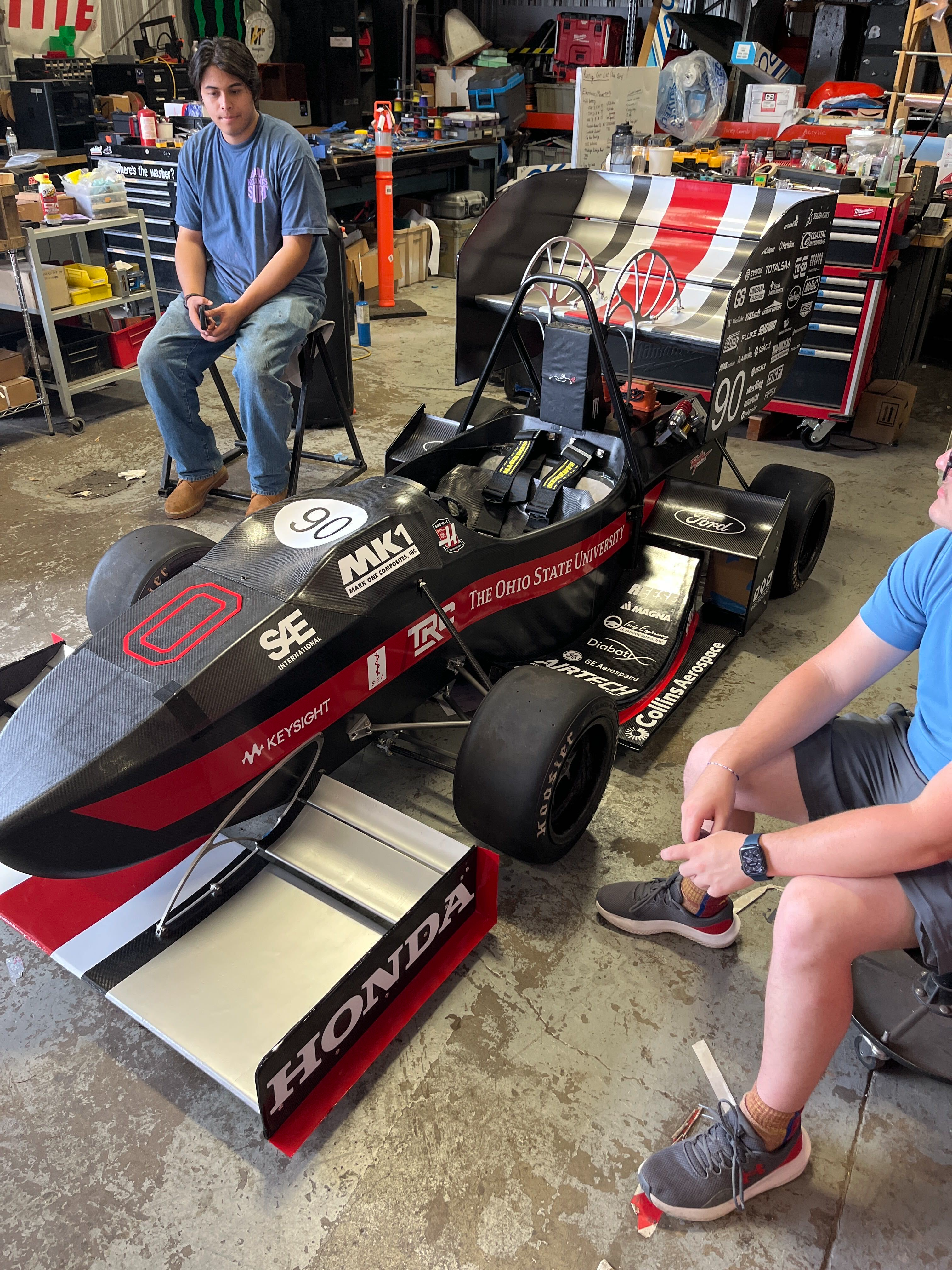
This documents the design of the FB26 Formula Buckeye FW & RW swan necks. Most of the screenshots shown come from a design review presentation given for both components as part of approval for manufacturing.
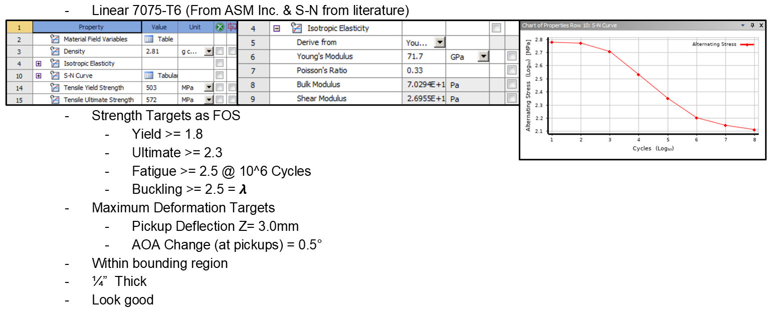
Before work began specific targets and constraints were set. Notably the material properties listed were compiled manually to create a linearized 7075-T6 aluminum material compatible with ANSYS topology optimization.
Load scenarios were defined from the maximum aerodynamic loads each wing would experience, combined with inertial loading from low and high speed scenarios of cornering while braking and cornering while accelerating. 2 mounts were used for each wing so a scenario for the left and right mount was considered in each instance. This gave a total of 8 load scenarios for the rear wing mounts, and 16 load cases for the front wing mounts, which has a high and low mounting position.
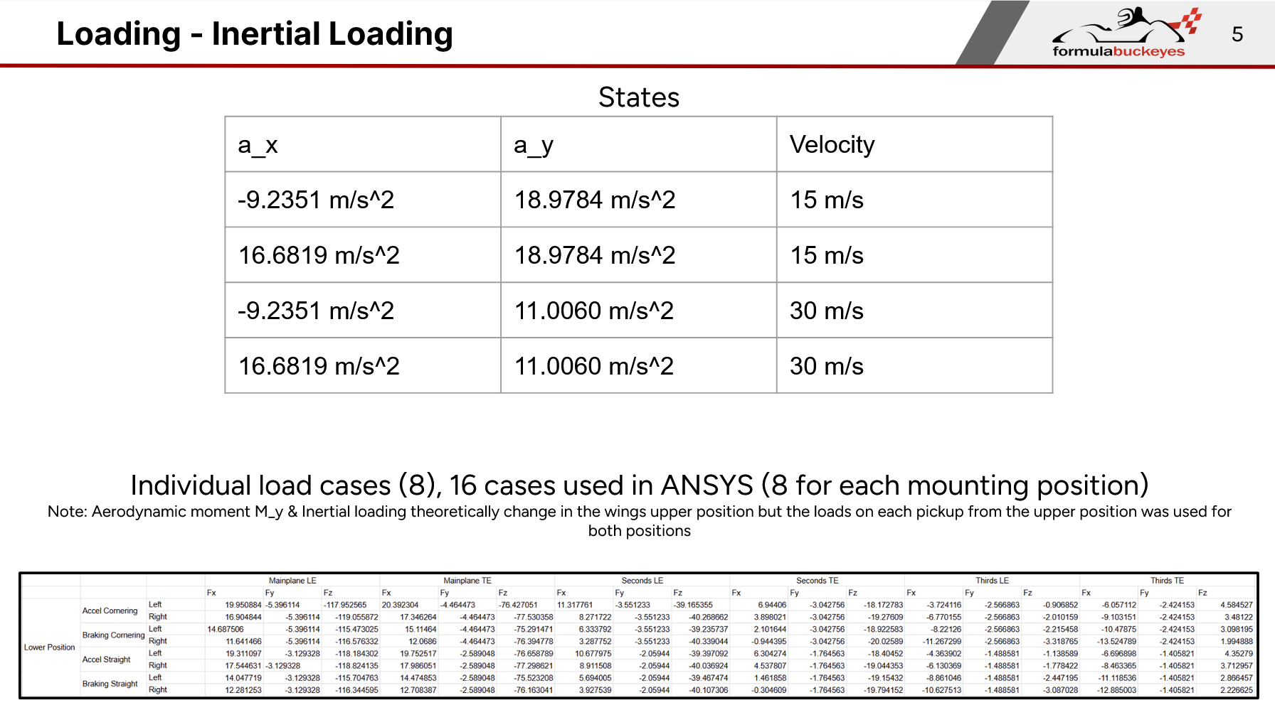
In a simplified case the rear wing loading scenarios can be represented by the equilibrium equations shown below (Vertical and horizontal loads only, no side loading for example purposes)
$M_y = F_{xLE} \cdot P_{1z} + F_{xTE} \cdot P_{2z} + F_{zLE} \cdot P_{1x} + F_{zTE} \cdot P_{2x}$
$F_x = F_{xLE} + F_{xTE}$
$F_z = F_{zLE} + F_{zTE}$
This system is not fully defined (even when properly expanded to loads in all 3 axes) and therefore we must find another way to solve it. This was done using the principle of least action, which requires finding the min norm solution to the system.
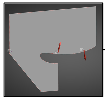 Working volume with pickup points shown
The solution was found using MATLAB.
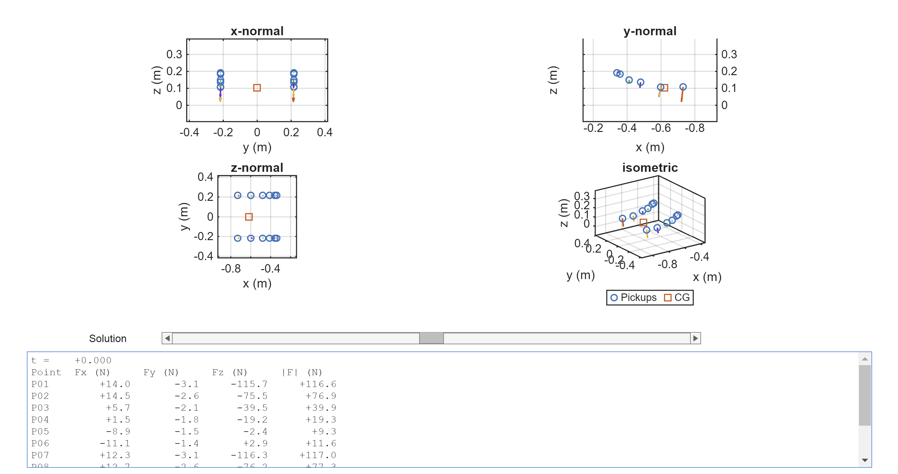 Script by Sam Patterson
Because the compute time of multi-case topology optimization scales ~linearly with the number of cases used, the two most extreme and different in direction load cases were used as static structural optimization input in ANSYS.
 Partial ANSYS Workbench Setup
The initial results of each topology optimization are shown below.
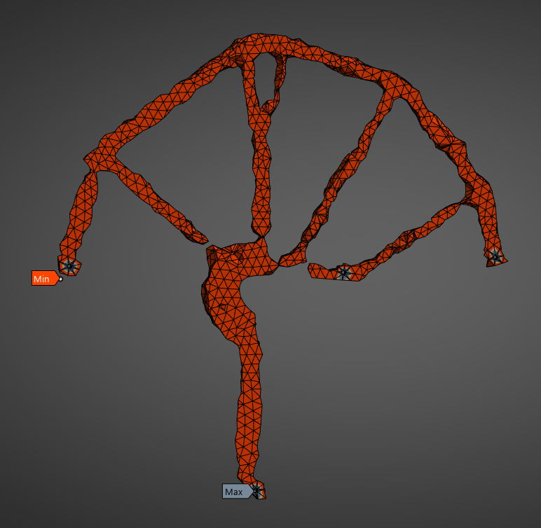

Multiple rounds with slightly different optimization constraints were run in order to avoid solutions which had converged arbitrarily due to a large working volume and low constraints. Between each round of topology optimization the areas of the part which had formed similar shapes in multiple runs were set as the new exclude boundary for the next run.
The a section of the methods used to justify the validity of the results for one mount are shown below.
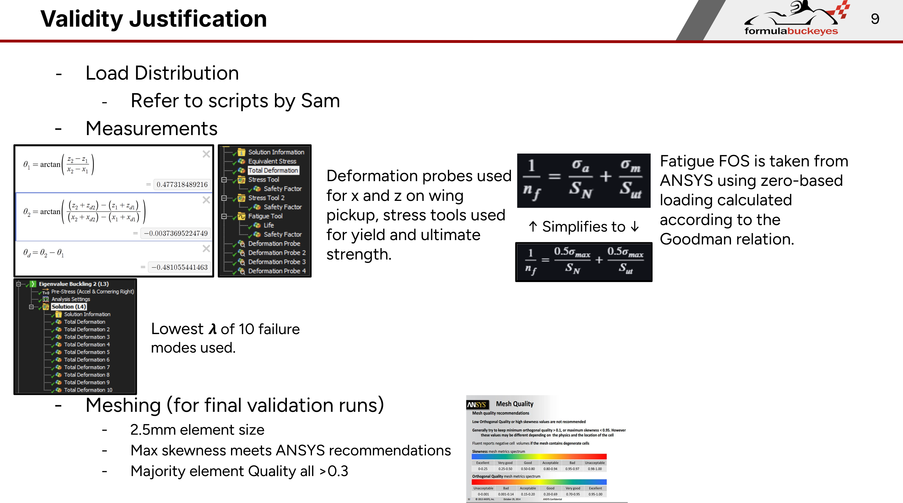
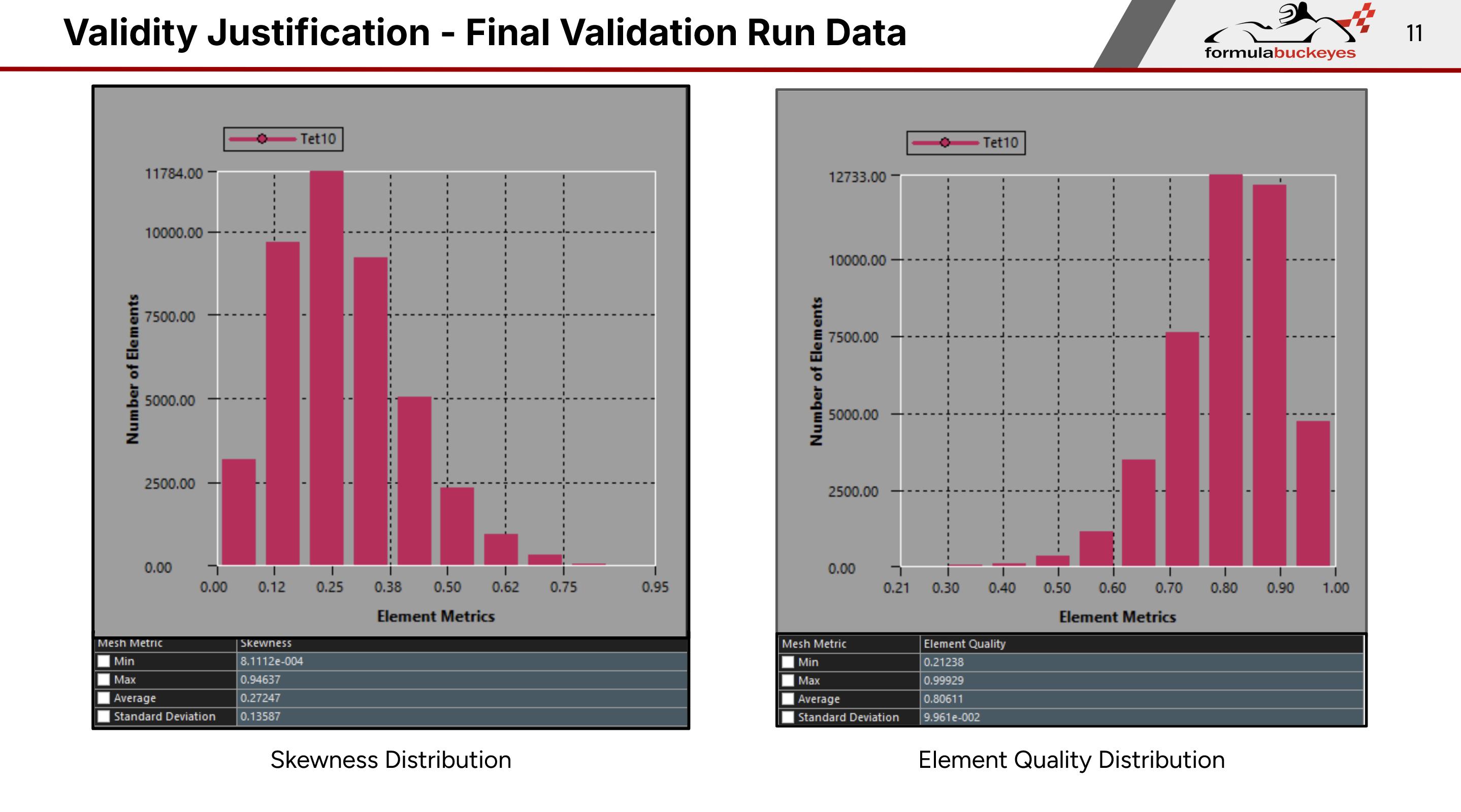
Finals designs were tested again all of the respective 8 and 16 original load cases, and a linear eigen buckling analysis for each case
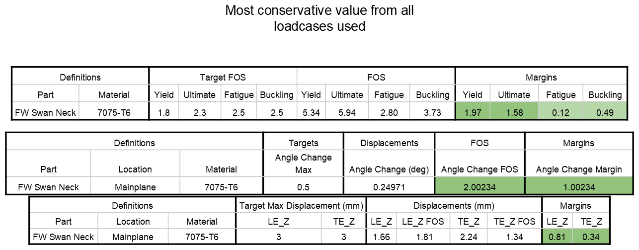 Front Wing Swan Neck Final Design Margin Table
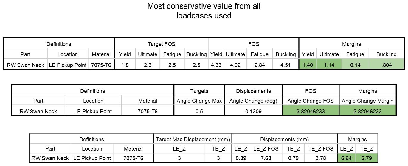 Rear Wing Swan Neck Final Design Margin Table